
Signals Configuration
The Signals section lets you define and wire three-aspect signal heads for your layout. Each signal maps red, yellow, and green LEDs to specific output pins on a hardware device, with support for both common anode and common cathode wiring. Signals can be controlled from the Throttle app or triggered by automation.
Signal List
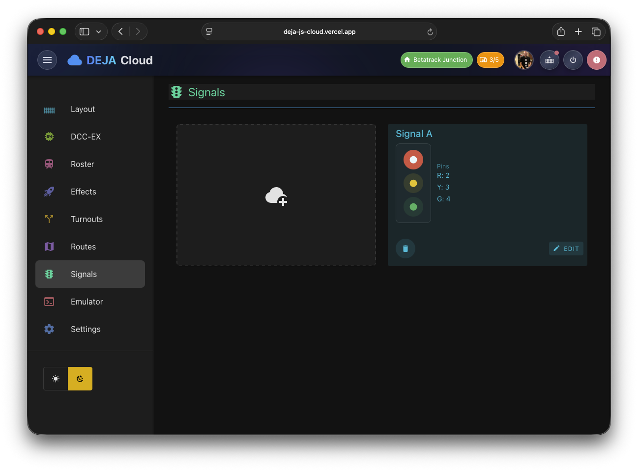
The main signals view (/signals) displays your signal heads as a list of cards. Each card shows the signal's name, its wiring type (common anode or common cathode), a chip for the controlling device, and a status dot colored by the current aspect. Cards also carry edit and delete actions, and the list can be filtered by device or tag. While the list loads, skeleton placeholders keep the layout steady.
Controlling Aspects from the List
Each card includes a miniature signal head — stacked red, yellow, and green buttons that set the aspect directly from the list, no edit form needed. The active aspect renders solid; tapping another aspect switches the signal immediately. Buttons are only enabled for aspects that have a pin configured, so a two-aspect red/green signal shows its yellow button disabled.
Adding a Signal
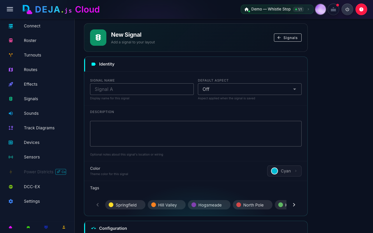
Navigate to /signals/new or click the Add tile. The signal form collects the following information:
Device Selection
At the top of the form, a device picker shows all hardware devices registered in your layout. When adding a signal, the picker renders as an inline grid so you can see every option at once; when editing, it collapses to a compact chip that opens a picker dialog. Select the device that physically controls this signal's LEDs. If only one device is configured, it is auto-selected.
A device is required -- the form will not submit without one because signals need a physical controller to drive their LED outputs.
Signal Details
| Field | Description | Required |
|---|---|---|
| Signal name | A display name for the signal (e.g., "East End Main", "Yard Entry") | Yes |
| Default aspect | The aspect applied when the signal is saved. Options: Off, Red, Yellow, Green | No |
Pin Configuration
Three pin fields map each signal aspect to an output pin on the selected device:
| Field | Color Indicator | Description |
|---|---|---|
| Red pin | Red circle icon | Pin number for the red LED |
| Yellow pin | Yellow circle icon | Pin number for the yellow LED |
| Green pin | Green circle icon | Pin number for the green LED |
Each field accepts a numeric pin number corresponding to the output pin on your hardware device. Pin numbers depend on your hardware -- for Arduino and ESP32 devices, these are typically digital output pins, and for Pico W devices, they map to GPIO numbers. For expansion boards, they may be I2C or shift-register addresses.
All three pins are optional -- you can configure a two-aspect signal by leaving one pin blank (for example, omitting yellow for a simple red/green block signal).
Wiring Type
A toggle switch selects between two wiring configurations:
- Common Cathode (default) -- The LEDs share a common ground. Each pin sources current to light the corresponding LED. This is the most common wiring for individual LED signal heads.
- Common Anode -- The LEDs share a common positive voltage. Each pin sinks current to light the corresponding LED. Some commercial signal modules use this wiring.
The toggle label dynamically displays the current wiring type ("Wiring: Common Cathode" or "Wiring: Common Anode").
Additional Fields
- Description -- An optional multi-line text area for notes about the signal's location, purpose, or wiring details.
- Color -- A color picker for the signal card's display color in the UI.
- Tags -- Assign tags for filtering and organization.
Validation
The form validates that:
- A signal name is provided.
- A device is selected.
If validation fails, an error alert is displayed at the bottom of the form.
Editing a Signal
Click any signal card in the list to navigate to /signals/:signalId. The edit form shows all the same fields, pre-populated with the existing signal configuration. The header displays "Edit Signal" instead of "Add Signal". Modify any fields and click Save Signal to persist changes, or Cancel to discard.
Aspect Wiring Reference
When you set a signal's aspect, DEJA.js drives the red, yellow, and green pins according to the wiring type you selected -- for common cathode, the active aspect's pin turns on while the others turn off; for common anode, this is inverted.
Aspect Truth Table (Common Cathode)
| Aspect | Red Pin | Yellow Pin | Green Pin |
|---|---|---|---|
| Red | HIGH | LOW | LOW |
| Yellow | LOW | HIGH | LOW |
| Green | LOW | LOW | HIGH |
| Off | LOW | LOW | LOW |
For common anode wiring, the HIGH/LOW values are inverted.
Signal Placement Tips
- Block signals -- Place signals at the entrance to track blocks to indicate occupancy. Use red for occupied, green for clear.
- Approach signals -- Use yellow to indicate that the next block is occupied, giving the engineer time to slow down.
- Interlocking signals -- Place signals at turnout junctions to indicate which route is set. Connect signal aspect changes to route execution for automated signaling.
- Two-aspect signals -- For simple block detection, configure only the red and green pins, leaving yellow blank.
Related Pages
- Effects Management -- Signals are conceptually similar to multi-pin effects.
- Layout Configuration -- Manage the hardware devices that drive your signals.
- Sensors -- Connect sensors to automate signal aspects based on train detection.